Comprehensive Guide to Air-Cooled Screw Chillers: Efficiency and Maintenance

Home / Blog / Industry News / Comprehensive Guide to Air-Cooled Screw Chillers: Efficiency and Maintenance

Comprehensive Guide to Air-Cooled Screw Chillers: Efficiency and Maintenance


Content

INDUSTRIAL COOLING ENGINEERING

Understanding Air-Cooled Screw Chiller Performance

An air cooled screw chiller combines screw compressor technology with an air-cooled heat rejection system to provide chilled water for industrial processes, commercial facilities, and large cooling installations. Its performance depends on compressor loading, condenser airflow, refrigerant conditions, water circulation, and the way the unit responds to changing thermal demand.

For plant engineers and equipment purchasers, selecting the right system requires more than comparing nominal cooling capacity. The practical objective is to maintain the required leaving-water temperature, control operating costs, prevent avoidable shutdowns, and preserve reliable performance throughout the equipment lifecycle.

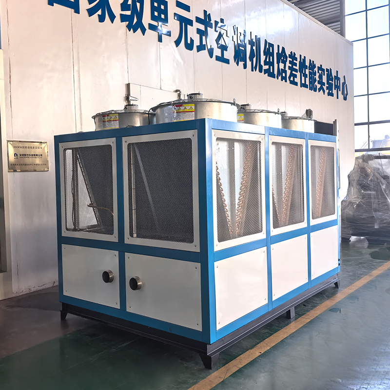
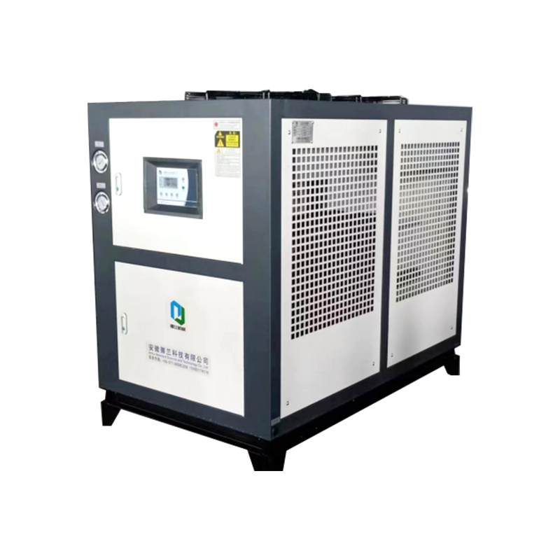
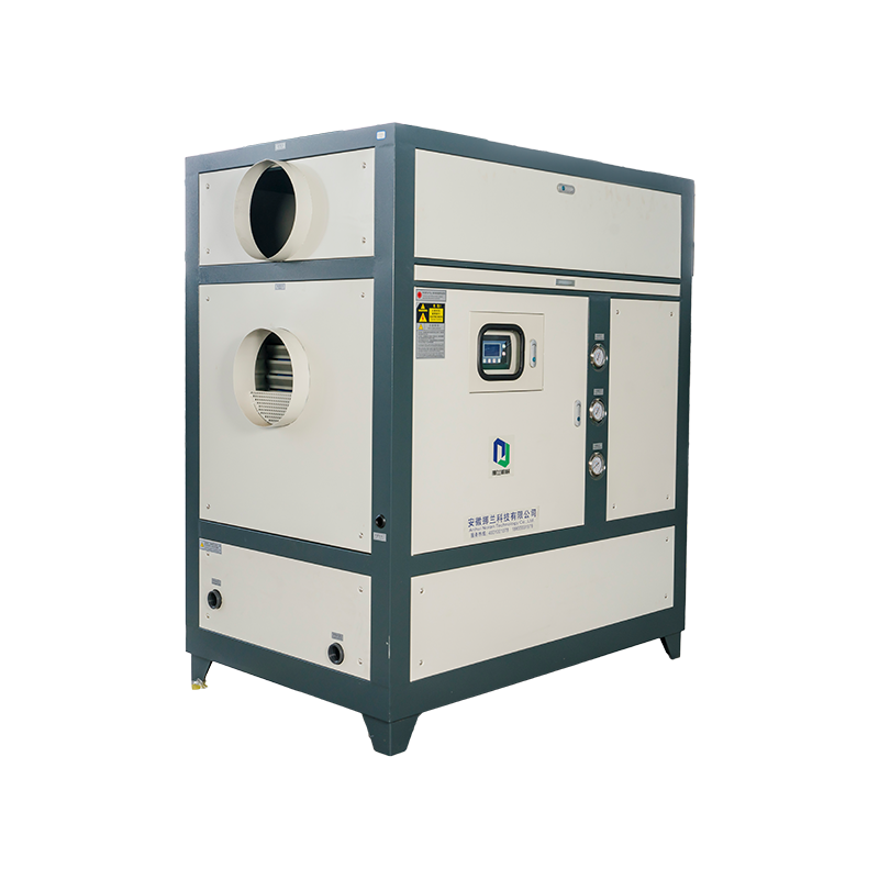
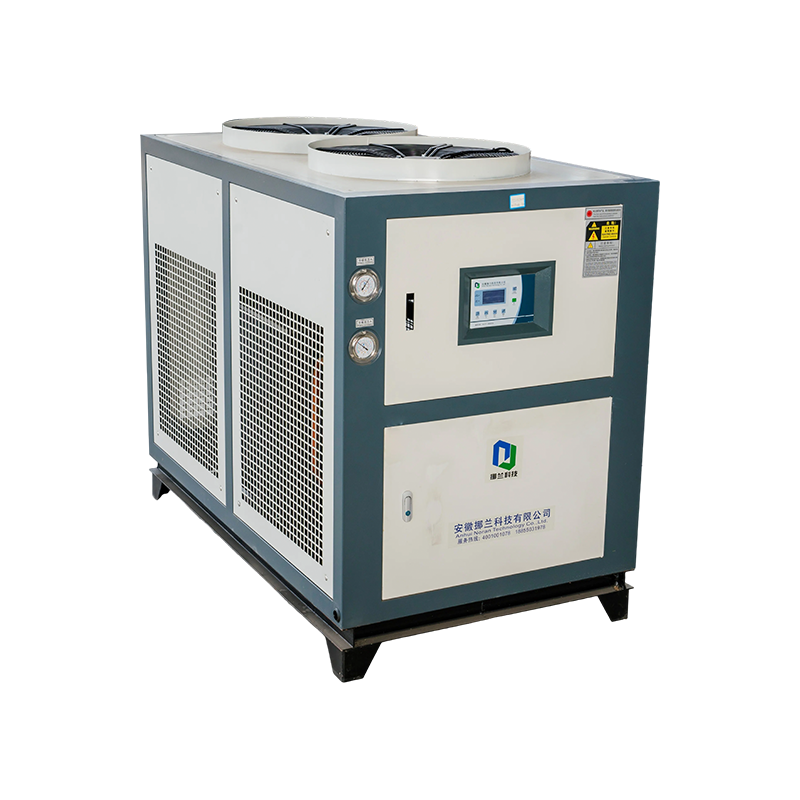
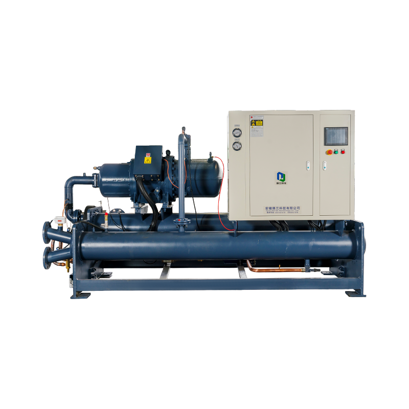
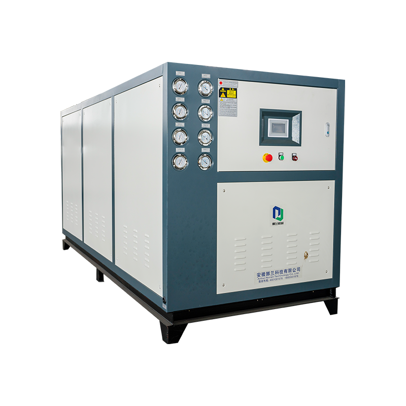
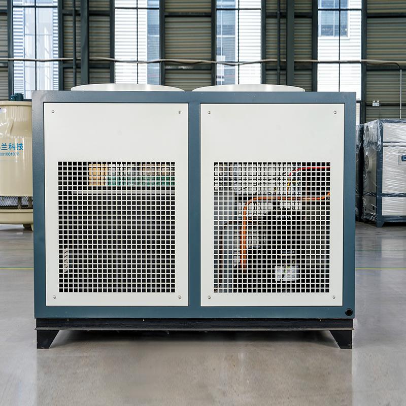
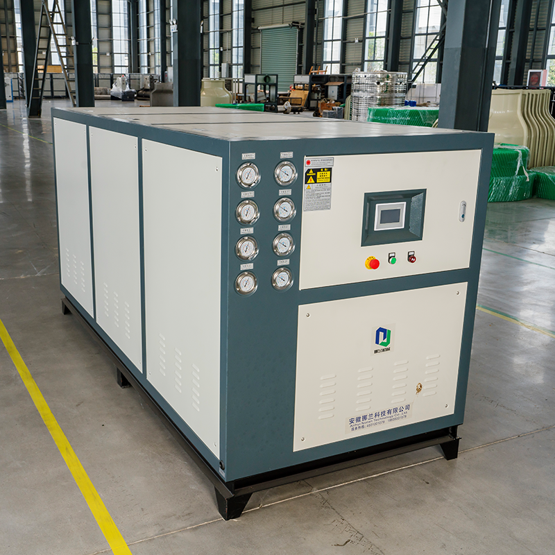
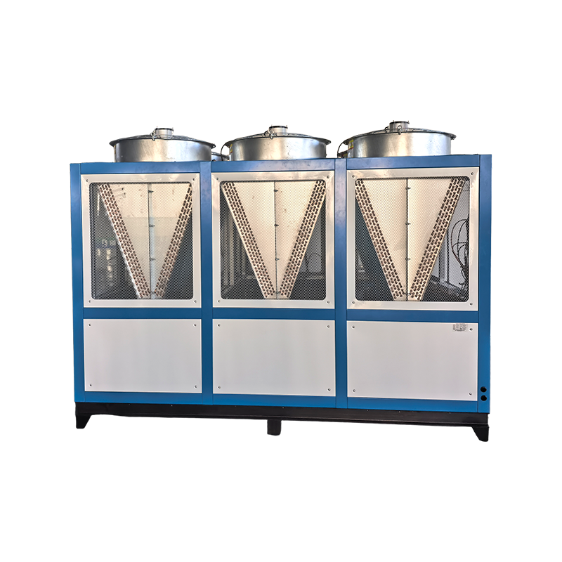
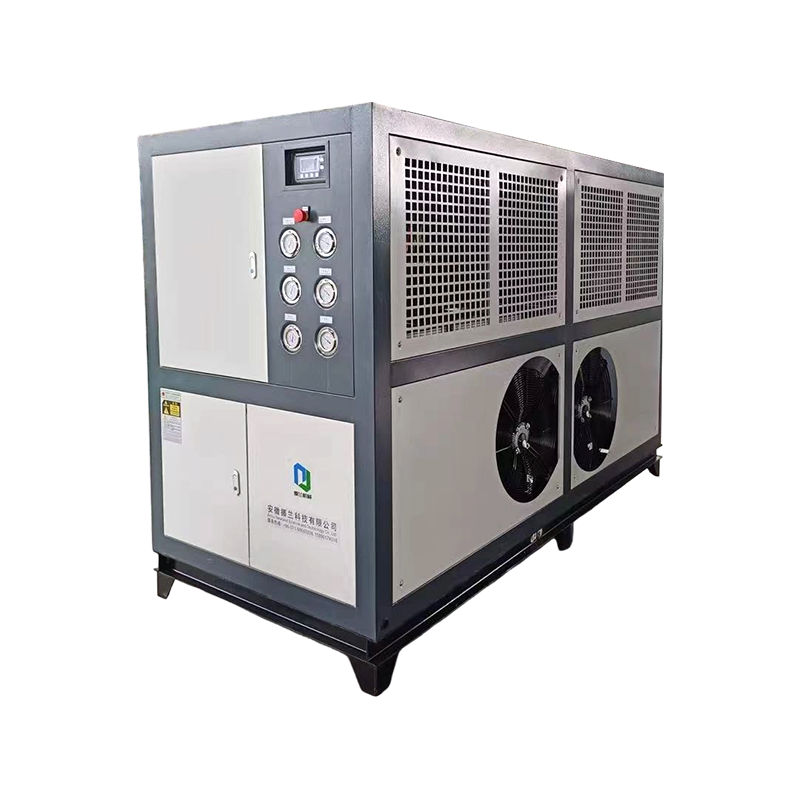
Industrial air cooled screw chiller equipment for process cooling

Air-cooled refrigeration equipment for industrial cooling applications

DESIGN PRIORITYCooling Capacity

Match the actual process heat load.

ENERGY PRIORITYPart-Load Efficiency

Evaluate performance across operating conditions.

RELIABILITY PRIORITYPreventive Care

Monitor temperatures, pressures, and airflow.

1. How an Air-Cooled Screw Chiller Works

An air-cooled screw chiller removes heat from a circulating liquid and transfers that heat to the surrounding air. The chilled liquid then returns to production equipment, heat exchangers, or air-handling systems. Unlike a water-cooled installation, the air-cooled arrangement rejects heat through outdoor condenser coils and fans rather than relying on a cooling tower and condenser-water circuit.

The refrigeration circuit typically contains a screw compressor, an oil management arrangement, a condenser, an expansion device, and an evaporator. Controls coordinate these components to maintain the required cooling output while protecting the compressor and other critical equipment.

01Evaporator

Refrigerant absorbs heat from the process liquid.

→
02Screw Compressor

Refrigerant vapor is compressed to a higher pressure.

→
03Air-Cooled Condenser

Fans move outdoor air across the coils to reject heat.

→
04Expansion Device

Refrigerant pressure is reduced before returning to the evaporator.

The screw compressor and capacity control

A screw compressor uses rotating helical rotors to compress refrigerant vapor. The continuous compression process makes this design suitable for many medium and large cooling duties where stable operation and adaptable capacity are important. Depending on the equipment design, capacity can be regulated through a slide valve, variable-speed drive, staged compressor operation, or a combination of control methods.

Capacity regulation matters because industrial heat loads rarely remain constant throughout the day. A production line may operate at full demand during a processing cycle and require much less cooling during changeovers. A correctly selected industrial screw chiller can adjust its output to these changes instead of repeatedly cycling in response to small variations in load.

The role of the condenser and evaporator

The evaporator transfers heat from the process liquid into the refrigerant. Its performance depends on liquid flow, heat-transfer surface condition, refrigerant distribution, and the required leaving-water temperature. Poor flow or fouling can reduce heat transfer and create unstable operating conditions.

The condenser releases absorbed process heat together with the energy added by the compressor. When outdoor air becomes hotter or condenser coils become obstructed, the system may need a higher condensing temperature to reject the same heat. Compressor power can consequently increase, and protective controls may limit output under severe conditions.

2. Key Factors That Determine Energy Efficiency

Energy efficiency is not a fixed characteristic independent of the installation. The same chiller can perform differently as outdoor temperature, process load, chilled-liquid temperature, airflow, and maintenance condition change. Reviewing these variables helps engineers distinguish equipment limitations from problems that can be corrected through operating adjustments.

A

Outdoor Air Temperature

Hot ambient conditions increase the temperature difference the condenser must manage. Appropriate equipment sizing, clear airflow paths, and clean coils help reduce unnecessary compressor work.

B

Leaving-Water Temperature

Lower required chilled-water temperatures generally increase refrigeration lift. Specify the warmest process temperature that still satisfies product quality and equipment requirements.

C

Part-Load Operation

Compressor unloading and variable-speed control can help reduce energy consumption when demand falls. The actual benefit depends on the control range and the unit's performance characteristics.

D

Condenser Airflow

Dust, leaves, blocked discharge paths, and recirculated hot air interfere with heat rejection. Correct clearance and regular coil inspection support stable operation.

E

Liquid-Side Performance

Incorrect flow, air trapped in the circuit, or deposits on heat-transfer surfaces can compromise cooling. Water treatment and flow verification should follow the system design.

F

Auxiliary Power

Condenser fans, chilled-water pumps, and controls also consume electricity. System-level evaluation should include these loads rather than considering compressor power alone.

Compare efficiency at realistic operating points

Nominal ratings are useful for initial screening, but they do not describe every operating condition. Request performance data at the design ambient temperature, required leaving-water temperature, entering-liquid temperature, and expected load range. Confirm whether the quoted electrical input includes condenser fans, pumps, or other auxiliary equipment.

Seasonal performance also matters. A factory operating mainly during cool nights may experience a different efficiency profile from a facility running continuously through hot afternoons. Performance data should reflect the intended operating schedule wherever possible.

Engineering note

Compare units under equivalent conditions. A higher nominal efficiency figure is not necessarily a better choice if the tested temperature conditions, included auxiliary loads, or available capacity range differ.

3. Visual Analysis of Cooling Efficiency Factors

The following charts use illustrative engineering scores and sample operating data to explain how common conditions influence chiller performance. They are not certified performance results for a particular model. Actual measurements and manufacturer selection data should be used for equipment evaluation.

Relative Impact of Common Efficiency Factors

Illustrative impact scores on a scale from 1 to 10. Higher values indicate a greater potential influence on energy performance.

Ambient heat Condenser fouling Water temperature Part-load control Liquid flow 9 8 7 6 5 0 2.5 5 7.5 10 Illustrative impact score

Use this ranking as a troubleshooting framework, not as a universal measurement. The dominant factor depends on the installation and its operating conditions.

Illustrative Energy Use Across Different Loads

Sample normalized daily energy consumption for one hypothetical installation. Values are shown as index points rather than measured kilowatt-hours.

100 75 50 25 0 25% 40% 60% 80% 100% Cooling load as a percentage of rated capacity

The curve represents a hypothetical relationship between load and total energy use. It does not indicate efficiency by itself because cooling output changes with load. Compare electricity consumption against delivered cooling over the same period.

Sample Monthly Energy Consumption

Illustrative monthly electricity consumption for a facility with changing production demand.

12 9 6 3 0 Jan Feb Mar Apr May Jun Month Energy index

A monthly chart is useful for identifying unexpected changes, but production volume, weather, operating hours, and delivered cooling should be reviewed before attributing a change to equipment efficiency.

4. Selecting the Right Chiller Capacity and Configuration

Correct sizing begins with the process heat load, not with a general rule based on factory floor area. Two facilities with similar floor space may have very different cooling requirements because their machinery, production schedules, incoming material temperatures, and allowable process temperatures differ.

Establish the actual cooling demand

Gather information from the process owner, equipment supplier, and facility engineer. Identify the maximum simultaneous cooling demand, normal operating load, expected future expansion, and any short-duration peaks. If multiple machines operate intermittently, determine whether their peak demands overlap or occur in separate production stages.

  • Required cooling capacity under the expected design conditions.
  • Entering and leaving liquid temperatures and permitted temperature variation.
  • Required liquid flow, system pressure drop, and connection requirements.
  • Outdoor design temperature and exposure to dust, moisture, or corrosive conditions.
  • Daily operating hours, seasonal demand, and planned production changes.
  • Available electrical supply, installation footprint, service clearance, and noise limits.

Oversizing can increase capital cost and may lead to less favorable operation if the unit cannot modulate efficiently at the plant's normal load. Undersizing can result in inadequate process temperature control during peak demand or hot weather. The selection should balance actual duty, capacity control, redundancy, and expected operating conditions.

Compare common equipment configurations

Configuration Typical consideration Selection priority
Air cooled screw cabinet chiller Packaged arrangement with integrated components, subject to model design Footprint, service access, and installation simplicity
Air cooled industrial screw chiller Industrial process duty with site-specific operating requirements Stable output, operating range, and maintainability
Large capacity air cooled chiller Higher cooling demand or multiple connected loads Capacity staging, airflow, and redundancy
Variable-speed screw chiller Load variation may justify speed modulation Part-load performance and control compatibility
Multi-unit installation Separate units can support staged operation and maintenance flexibility System integration, isolation, and backup capacity

For a large facility, several smaller units may provide operational flexibility, while a single larger unit may reduce the number of equipment packages and connections. Neither arrangement is universally superior. Evaluate part-load behavior, service requirements, electrical infrastructure, and the consequences of losing one unit.

5. Comparing Performance Across Operating Conditions

Different chiller configurations should be assessed against the same operating requirements. A screw compressor chiller designed for industrial process duty may prioritize continuous operation and adjustable capacity, while an HVAC air cooled chiller may be selected around building cooling schedules and distribution conditions. These descriptions overlap, so actual equipment specifications are more useful than the application label alone.

Illustrative Configuration Comparison

Relative suitability scores for a hypothetical selection exercise. Scores are not product ratings and should be replaced with verified technical data.

Part-load control Installation Capacity range Service access Process stability Configuration A Configuration B Configuration C

Use a radar comparison to organize weighted selection criteria. A final decision should also consider purchase price, lifecycle cost, certified capacity, warranty terms, local service capability, and site-specific constraints.

Assess total operating cost

The purchase price is only one component of lifecycle cost. Electricity consumption over the expected service period can be a major expense, particularly when the chiller operates for long shifts or supports a continuous process. Maintenance labor, replacement parts, refrigerant management, downtime, and any required water treatment should also be considered.

Ask suppliers to explain their test conditions and provide performance information at representative load points. Review the proposed control sequence and confirm whether the unit can maintain process temperatures at minimum demand without excessive cycling. For critical production, consider the cost of interrupted cooling as part of the selection rather than treating reliability as a secondary feature.

6. Installation Planning and System Integration

Even a well-selected unit can underperform if installation conditions restrict heat rejection or create unstable liquid circulation. The installation plan should cover physical access, structural support, electrical protection, drainage where required, piping design, and coordination with production controls.

Outdoor location and condenser airflow

Place the unit where condenser fans can draw in fresh air and discharge heated air without obstruction. Follow the manufacturer's minimum clearance requirements around coils, fan outlets, service panels, and neighboring structures. Walls, fences, rooftop enclosures, and closely grouped equipment can create recirculation zones that increase entering-air temperature.

Consider prevailing wind, rooftop exposure, nearby exhaust outlets, airborne fibers, and seasonal debris. An apparently open location can still experience poor performance if hot air is repeatedly drawn back through the condenser. Where several chillers are installed together, review their combined airflow patterns rather than checking each unit in isolation.

Liquid piping and hydraulic stability

Design the chilled-liquid circuit to provide the required flow through the evaporator under all intended operating modes. Select pumps and piping based on pressure drop, elevation, valve arrangement, and the needs of connected equipment. Confirm that strainers, balancing devices, and isolation valves can be inspected and serviced.

Where the process has rapidly changing demand, a buffer tank or an appropriate control strategy may help limit temperature fluctuations and compressor cycling. Its suitability depends on system volume, load profile, minimum run-time requirements, and the chiller's control capabilities. Insulate cold piping and fittings to limit heat gain and condensation.

Electrical and control integration

Verify supply voltage, phase configuration, available fault protection, cable sizing, and starting or drive requirements with qualified electrical personnel. Coordinate alarms, remote enable signals, operating status, and temperature feedback with the plant monitoring system. Define how the chiller responds to communication loss, low flow, abnormal temperatures, and emergency shutdown requests.

Before commissioning, document the design operating points and establish baseline readings. Record leaving-liquid temperature, entering-liquid temperature, flow, ambient conditions, compressor loading, fan status, and electrical consumption where measurement is available. These records make later fault diagnosis more reliable.

7. Preventive Maintenance for Reliable Operation

Maintenance should focus on preserving heat transfer, maintaining stable refrigerant operation, verifying protection devices, and identifying changes before they become failures. The following schedule is a planning framework. Actual intervals must follow the equipment manual, site conditions, operating hours, and applicable safety requirements.

DAILY OR EACH SHIFT

Review operating conditions

Check alarms, leaving-liquid temperature, visible leaks, abnormal vibration, unusual sound, and fan operation. Compare readings with the established operating baseline.

WEEKLY

Inspect airflow and surroundings

Remove loose debris from accessible areas, check that air passages remain clear, and look for new obstructions or evidence of coil damage. Follow safe isolation procedures before cleaning.

MONTHLY

Review system trends

Examine temperature and pressure trends, liquid flow indications, electrical consumption, alarm history, and changes in operating hours. Investigate unexplained deviations rather than repeatedly resetting alarms.

SEASONAL

Prepare for ambient changes

Inspect condenser condition before periods of high outdoor temperature. Verify fan operation, drainage, weather protection, and operating settings appropriate to the manufacturer's instructions.

SCHEDULED SERVICE

Complete technical inspections

Have qualified personnel inspect electrical connections, compressor operation, refrigerant circuit condition, safety controls, oil management components where fitted, and other service items specified by the manufacturer.
Condenser coil cleaning

Dirty condenser coils restrict airflow and reduce heat transfer. The appropriate cleaning method depends on coil construction, fin spacing, contamination, and the manufacturer's instructions. Use approved methods and suitable tools to avoid bending fins or damaging protective coatings. High-pressure washing should not be used unless specifically permitted and properly controlled.

Facilities exposed to dust, paper fibers, oil mist, or other airborne contaminants may require more frequent inspections than clean indoor industrial environments. Establish the interval through observed coil condition and changes in operating performance rather than relying on a fixed calendar alone.

Refrigerant and compressor monitoring

Changes in suction and discharge conditions, superheat, subcooling where specified, oil condition, and compressor temperature may indicate developing problems. These readings must be interpreted together and compared with approved operating envelopes. No single pressure or temperature reading should be used to diagnose a fault without considering ambient conditions and cooling load.

Refrigerant leak inspection, circuit repairs, refrigerant recovery, and charging must be performed by appropriately qualified personnel using suitable equipment and procedures. Do not release refrigerant deliberately or bypass protective controls to keep the machine running.

Liquid circuit maintenance

Verify flow and check strainers, pump performance, air removal, and signs of corrosion or deposits. The required water quality depends on the liquid circuit, metallurgy, operating temperatures, and whether the system uses treated water, glycol, or another approved fluid. Follow the equipment specifications and the site's water management procedures.

For glycol systems, confirm the specified fluid concentration and condition through appropriate testing. Excessive concentration can affect heat transfer and pumping requirements, while inadequate freeze protection can expose the evaporator and connected piping to damage in low-temperature conditions.

8. Troubleshooting Common Performance Problems

A structured diagnostic process reduces unnecessary component replacement and helps maintenance teams identify the cause of recurring alarms. Begin with the operating history and compare current readings against the commissioned baseline. Observe safety procedures and use qualified service personnel for refrigerant, electrical, and compressor work.

Observed symptom Potential causes Recommended investigation
High discharge pressure Restricted airflow, hot ambient conditions, dirty coils, fan problems, or a refrigerant circuit issue Verify ambient conditions, fan operation, coil cleanliness, and approved pressure readings.
Insufficient cooling Excess process load, low liquid flow, heat-transfer problems, or reduced refrigeration capacity Confirm process demand, entering and leaving temperatures, flow, and compressor status.
Frequent cycling Low system volume, control settings, unstable load, or an operating fault Review run times, load variation, buffer arrangements, and control parameters.
Unusual vibration or noise Loose components, fan imbalance, mounting issues, or mechanical deterioration Check safe external inspection points and arrange a technical inspection if the condition persists.
Unexpected electricity use Changed production demand, elevated ambient temperature, fouling, or control issues Normalize consumption against operating hours and delivered cooling, then inspect trends.
Evaporator freeze risk Low flow, low load, incorrect settings, or inadequate fluid protection Follow the shutdown procedure and investigate flow, sensors, control settings, and fluid condition.

Follow a consistent diagnostic sequence

Identify alarm or performance change Is cooling demand normal? No Check process load and schedule Yes Check airflow, flow, and sensors Compare trends with baseline and equipment limits Escalate unresolved faults to qualified service personnel

Stop the equipment when required by its safety controls or operating instructions. Persistent high-pressure alarms, suspected refrigerant leakage, electrical burning odors, severe vibration, or possible freezing should not be managed by repeated resets. Document the fault code, operating conditions, recent changes, and actions already taken before requesting technical support.

9. Using Monitoring Data to Improve Efficiency

Routine monitoring turns maintenance from a calendar-based task into a more informed process. Even a simple record of outdoor temperature, liquid temperatures, operating hours, compressor loading, and electricity consumption can reveal patterns that would otherwise remain unnoticed.

Establish a useful performance baseline

Record the equipment's operating conditions after commissioning and after major maintenance. Include the process load or an appropriate production indicator, because energy consumption alone can be misleading. A month with higher electricity use may simply reflect longer production hours or greater cooling demand.

Where suitable metering is available, compare electricity use with delivered cooling over matching intervals. Keep the measurement boundary consistent: if one reading includes pumps and fans while another includes only the compressor, the values cannot be compared directly. Document any changes to instrumentation or calculation methods.

Use alarms and trends constructively

  • Set alarm thresholds according to the approved operating envelope and process risk.
  • Review repeated warnings to identify recurring environmental, hydraulic, or control issues.
  • Track compressor starts and run times to identify unnecessary cycling.
  • Compare similar production periods when evaluating changes in energy performance.
  • Retain maintenance records and verify whether corrective work improves the expected indicators.

Advanced monitoring can help identify gradual degradation, but it does not replace physical inspection or competent diagnosis. Sensors may drift, control systems may use filtered values, and unusual process conditions may resemble equipment faults. Confirm important findings before changing settings or replacing components.

10. Working With a Chiller Manufacturer or Supplier

When evaluating an air cooled screw chiller manufacturer or supplier, request enough technical information to verify that the proposed equipment fits the actual application. Clear operating requirements make quotations easier to compare and reduce the risk of purchasing a unit that meets a headline capacity figure but cannot satisfy the required duty under site conditions.

Technical information to request

  • Cooling capacity and electrical input at the specified design conditions.
  • Performance information at representative part-load operating points.
  • Required entering and leaving liquid temperatures and flow conditions.
  • Permitted ambient operating range and any capacity derating at high temperatures.
  • Compressor type, capacity-control method, and applicable protection functions.
  • Condenser fan arrangement, service clearances, dimensions, and operating sound data.
  • Electrical requirements, control interfaces, alarms, and communication options.
  • Recommended maintenance intervals, spare parts availability, and warranty conditions.

When customization is appropriate

A custom air cooled screw chiller may be appropriate when standard configurations cannot satisfy the required liquid temperature, ambient range, control interface, footprint, electrical supply, or environmental conditions. Customization should begin with a documented technical requirement rather than an open-ended request for additional features.

Review the impact of requested changes on capacity, operating range, lead time, maintenance access, and component availability. Confirm which items are standard, which are optional, and which require engineering validation. For special process conditions, request written confirmation that the proposed configuration can maintain the required duty across the intended operating envelope.

Evaluate support over the equipment lifecycle

Supplier evaluation should include documentation quality, commissioning support, access to replacement parts, service response arrangements, and the availability of qualified technicians. For a critical production process, clarify which spare parts should be kept on site and how faults will be escalated outside normal working hours.

Before accepting the installation, verify the agreed operating conditions, alarm functions, water flow, electrical readings, and temperature control behavior. Keep commissioning records and ensure operators understand routine checks, shutdown requirements, and escalation procedures. These steps create a common reference for future maintenance and performance reviews.

11. Practical Efficiency Improvement Checklist

The following checklist helps plant teams prioritize improvements without making unsupported assumptions about potential energy savings. Start with items that can be verified through inspection and operating data, then evaluate more complex control or equipment changes.

01
Confirm the real process load

Compare installed capacity with measured demand and the required temperature range.

02
Restore unrestricted condenser airflow

Remove obstructions and address recirculation in accordance with installation requirements.

03
Verify liquid-side conditions

Check flow, strainers, air removal, insulation, and heat-transfer surface condition.

04
Review control settings

Check temperature setpoints, capacity modulation, minimum run times, and alarm history.

05
Measure energy consistently

Include the same equipment loads and compare similar production and ambient conditions.

06
Plan maintenance before peak demand

Complete inspections and address known issues before periods of heavy cooling duty.

After each corrective action, record the change and review subsequent operation under comparable conditions. If performance does not improve as expected, revisit the diagnosis rather than assuming that the intervention was effective. For persistent issues, obtain a qualified assessment of refrigeration, airflow, hydraulics, and controls as a complete system.

12. Frequently Asked Questions

Q1: What is an air-cooled screw chiller?

An air-cooled screw chiller is a refrigeration system that uses a screw compressor to circulate refrigerant and an air-cooled condenser to reject heat outdoors. It cools water or another approved process liquid for industrial, commercial, and HVAC applications.

Q2: What affects air cooled screw chiller efficiency most?

Outdoor temperature, required leaving-liquid temperature, compressor loading, condenser airflow, liquid-side heat transfer, and auxiliary power all affect performance. Their relative importance depends on the operating conditions and equipment design.

Q3: Is a screw chiller suitable for continuous factory operation?

It can be suitable when its capacity, operating envelope, compressor controls, heat exchangers, and protection functions match the process requirements. Continuous-duty suitability should be confirmed using the manufacturer's technical documentation and the actual site conditions.

Q4: How often should an air-cooled condenser be cleaned?

The interval depends on airborne dust, fibers, oil mist, outdoor debris, operating hours, and observed coil condition. Inspect it regularly and follow the manufacturer's cleaning instructions rather than applying one interval to every installation.

Q5: Why does chiller energy consumption rise in hot weather?

Higher outdoor temperatures make heat rejection more demanding and can increase compressor power. Condenser fouling, restricted airflow, and hot-air recirculation can intensify this effect. Compare readings under similar cooling loads before deciding whether the change is abnormal.

Q6: Is a larger-capacity chiller always better?

No. Excess capacity can increase purchase costs and may cause inefficient cycling when demand is low if capacity control is unsuitable. Select equipment using the actual peak load, normal operating range, future requirements, and the manufacturer's performance data.

Q7: What is the difference between an air-cooled and water-cooled screw chiller?

An air-cooled screw chiller rejects heat through air-cooled condenser coils and fans. A water-cooled screw chiller transfers heat to a condenser-water circuit, typically connected to a cooling tower or another heat-rejection system. Installation resources, ambient conditions, water management, and energy performance influence the choice.

Q8: Can a screw chiller operate efficiently at partial load?

Yes, depending on its compressor design, capacity-control range, operating conditions, and system integration. Request verified part-load performance data and confirm that the unit can match the facility's typical cooling demand without excessive cycling.

Q9: What information is needed to select a chiller for process cooling?

Prepare the required cooling capacity, entering and leaving liquid temperatures, flow rate, ambient design temperature, operating schedule, load profile, electrical supply, installation restrictions, and any special fluid or environmental requirements. These details support an accurate technical selection.

Q10: When should a chiller be inspected by a qualified technician?

Arrange a technical inspection for persistent alarms, suspected refrigerant leakage, abnormal compressor conditions, unusual vibration, recurring high-pressure trips, or unexplained cooling loss. Follow the equipment's safety instructions and do not bypass protective devices to maintain operation.