Content
A 250 kW water-cooled chiller that holds a 2.8 K approach temperature in its first year often drifts to 5 K by year three. Nothing has failed, no alarm has tripped, and the refrigerant charge is correct. The compressor simply needs more lift to reach the same chilled-water setpoint, and the power meter records the change: typically 8 to 12 percent more electricity for identical cooling output. That gap is heat exchanger efficiency slipping away, and in industrial cooling loops it usually escapes through three predictable routes: fouling on the heat transfer surface, uneven flow distribution, and a unit that was sized for a duty it never actually sees.
Heat exchanger efficiency measures how close a unit comes to the maximum heat transfer its inlet temperatures allow, and it appears in two different numbers that engineers and buyers regularly confuse.
The figure printed in rating tables is effectiveness, a dimensionless ratio. The second figure, thermal efficiency, is the one that surfaces in energy reports and utility bills. They answer different questions. A specification that mixes them will produce a unit that meets its datasheet and still misses its operating target.
Effectiveness is useful because it can be verified on site at commissioning. Four temperature readings and two flow rates are enough to confirm whether the exchanger performs as rated. Typical values run from 0.45 for a compact finned coil to 0.95 for a well-configured plate unit in clean service.
A ratio between 0 and 1 that compares real heat transfer with the thermodynamic maximum for the given inlet conditions. It says nothing about pumping power, so a highly effective unit can still be expensive to run.
Relates delivered duty to ideal duty, then adds the cost of achieving it: pressure drop on both sides, pump energy, and in refrigeration cycles the extra compressor lift needed to cover a widening approach.
The practical consequence is simple. A coil can be 0.90 effective and still consume more plant energy than a 0.85 unit with half the air-side pressure drop, because the second unit lets the compressor run closer to its design point.
Log mean temperature difference, overall heat transfer coefficient, approach temperature and pressure drop determine the final efficiency of any exchanger, and all four should be fixed before a purchase order is signed.
| Exchanger type | Typical effectiveness | Typical U, W/(m2 K) | Best fit |
| Gasketed plate | 0.85 to 0.95 | 3000 to 7000 | Clean fluids, tight approach, compact footprint |
| Shell-and-tube, two pass | 0.60 to 0.80 | 800 to 1500 | High pressure, fouling fluids, heavy duty |
| Finned-tube air coil | 0.45 to 0.70 | 25 to 60 on the air side | Refrigeration, air cooling, cold rooms |
| Double-pipe | 0.70 to 0.85 | 700 to 1200 | Small flows, high pressure, simple duty |
Each 0.0001 m2 K/W of added fouling resistance removes about 9 percent of the capacity of a coil rated at 1000 W/(m2 K).
A supplier who quotes surface area alone has not shown you efficiency. Ask for the U value, the design fouling factor, the pressure drop on both circuits, and the flow rate used in the calculation. Those four figures make competing offers comparable.
Fouling is the first loss in nearly every open cooling loop, and it becomes measurable within weeks of startup rather than years.
Scale, biofilm and suspended solids build a resistance layer on the water side. A 0.1 mm layer of calcium carbonate is thin enough to pass a visual inspection and thick enough to disturb the whole rating. The chart below indexes coil capacity against scale thickness for a typical industrial cooling water circuit.
The pattern explains a familiar complaint: capacity feels fine in spring and short in August. The unit did not change, the load did, and the margin the designer built in has already been spent on scale.
The second loss is loop design. Open towers absorb airborne debris and concentrate dissolved solids through evaporation, so the exchanger inherits every chemistry problem the tower creates. A closed-circuit tower keeps the process fluid isolated in a sealed coil and pushes the fouling burden onto a surface that is easier to clean.
 Square Closed-Circuit Cooling Towers for Industrial Process CoolingKeeps process fluid isolated in a sealed coil, shifting fouling to a cleanable surface while supporting large, centralized industrial cooling duties.View Product →
Match the exchanger to the fluid first and to the duty second, because the wrong geometry loses more efficiency than a slightly undersized unit of the right type.
For air-side cooling in refrigeration and cold-room service, fin pitch and tube row count set the balance between heat transfer and air-side pressure drop. Wide fin spacing survives frost and dust; tight spacing raises capacity in clean duty and chokes in dirty duty. For water-side duties above 1500 kPa, a shell-and-tube stays the safer choice even though a plate would transfer more heat per square metre.
In a plastics injection molding plant the mould cooling circuit is the usual bottleneck: supply water arrives a few kelvin warm, cycle times stretch, and the chiller is blamed. Re-circuiting the coil so that chilled water enters at the coldest end of the mould loop often recovers the lost approach without adding capacity.
Anhui Noran Technology Co., Ltd. builds high-efficiency copper tube and aluminium fin cooling coils in which tube spacing, fin pitch and circuit arrangement are configured to the load profile rather than chosen from a catalogue default.
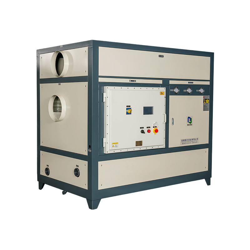 Noran Surface Cooler for Chiller-Based Air CoolingUses existing chilled water through copper tubes and aluminum fins to deliver cool air, enabling a cost-effective retrofit without a new chiller.View Product →
Most plants recover 10 to 25 percent of lost cooling capacity without replacing the chiller, because the loss usually sits in the exchange path rather than in the compressor.
Hydraulic and lubricating oil circuits follow the same logic with a different fluid. Oil carries heat poorly compared with water, so a dedicated oil chiller with a generously sized exchanger holds viscosity in the stable band and keeps bearing temperatures predictable through long shifts.
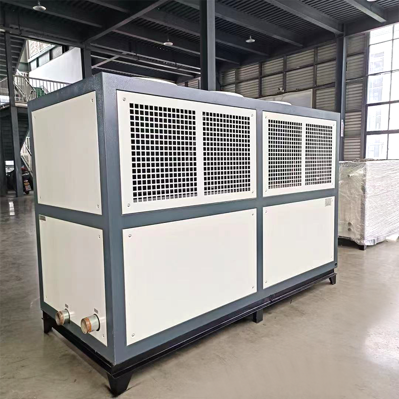 Air-Cooled Oil Chillers for Stable Industrial Oil TemperatureMaintains cooling oil within a stable temperature range without a cooling tower, helping protect machining and hydraulic equipment through long shifts.View Product →
No. Effectiveness measures heat transfer only. A unit with 0.95 effectiveness and a 90 kPa pressure drop can consume more plant energy than a 0.85 unit with a 30 kPa drop, because pump and fan power scale with the square of flow.
Inspect quarterly and clean when the measured approach temperature rises by 1 K above the commissioning value, or when scale reaches 0.1 mm. Waiting for a capacity complaint usually means the fouling layer has already reached 0.3 mm or more.
Use 0.0001 m2 K/W for softened or demineralised water, 0.0002 for treated cooling tower water, and 0.0003 or higher for river water or streams carrying suspended solids. Under-specifying this figure is the most common reason an exchanger misses its rating within two seasons.
It can be oversized in surface area while undersized in flow velocity. Very low velocity allows fouling to settle and reduces the mass transfer that keeps surfaces clean, so the correct target is a velocity band, typically 0.9 to 1.8 m/s on the water side, not maximum area.
Efficiency decisions are easier with real drawing data in front of you. Send the duty, fluid and site conditions to the engineering team and compare a sized proposal against your current measured performance.



Contact Us

Jenny@nolantech.cn
amy.wang@nolantech.cn
cici.yuan@nolantech.cn

+86-4001001078

+86-15990174016

+86-13677629472

+86-13677629472 (Amy) / +86-18226838248 (Cici)

No.60 Harmony Road,Green Coating Supporting Industrial Park, Mingguang City,Chuzhou City,Anhui Province, China
Ready to Begin?
Get in Touch

Now!
Custom Industrial Cooling Equipment Manufacturers

ANHUI NORAN

 English
 Français
 Español
 Português
 عربى
 Türk
 हिंदी
